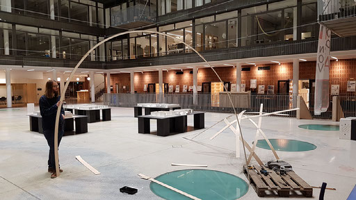
In the course Digital Tools and Parametric Design we wanted to have workshop together with our friends at BIG Engineering, Buro Happold and CORE studios at Thornton Tomasetti. We decided to try to build a 11x11 meter big geodesic gridshell in plywood. Geodesic gridshells are based on that you can build it using straight planar elements that can be bent and connected into the correct form or shape, if modelled correctly. This due to that geodesics only have curvature in the normal of the surface, and can therefore be "unrolled" as straight, you can make a geodesic by taking a piece of tape and paste onto a shape without wrinkles. The geodesic gridshell works the same but the tape is then a material like thin metal plates or thin plywood for instance. You can create geodesics by either specifying its start and end point or its starting point a direction on the surface. Below is our digital and physical prototyping stage where me and Isak test to see if this was possible.
You can read more about the course at http://emiladiels.com/digital-tools-parametric-design-course-2017/ and you can see the final workshop at http://emiladiels.com/geodesic-gridshell-workshop-2017/
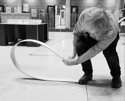
Physical prototyping
This stage we wanted to compare workability and the stiffness of the plywood laths. We also wanted to see how close we could place the connections and do some hands on analysis on bending and twisting the laths. Our tests shows that we could bend them pretty easily and that the curvature for breackage was pretty high, which meant that we would not need a very detailed analysis. It was also very flexible for twisting. We tried different widths of the laths; 50 mm, 70mm and 100 mm. The 50 mm was very slim and we really liked the apperance for it, The 100 mm was way to wide, and we could save a lot of money going to half size since could double or laths from one plywood board.
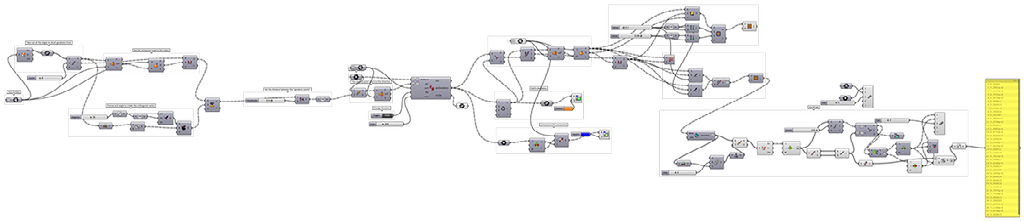
Digital prototyping
We also needed test our software to see if we can accually make the geodesics sufficiently on the shape and unroll them straight. We used the software I had written for an earlier paper for the IASS2017 where I made geodesic coordinates to used for brick patterns. I modified it a bit to give more control and also evaluated it against some inbuilt functionality in Rhino and Grasshopper. The reason we could not use theirs is because wanted controll the starting direction rather than the end points of the geodesics. It worked really nice, we even got better results if we used a really high resolution of our geodesics.